N62 Z3 Part 16: Test Fit & Dual Intake Install
- Graham
- May 17, 2021
- 9 min read
Updated: Jun 14, 2021
With the chassis fabrication done it was time to test fit the engine before prettying thing up, just in case things have to be modified further. I do not have the flywheel yet but I bolted things up for test fit purposes. I can also mock up engine mounts and etc while I continue to look for someone who can balance my V8 flywheel
First things first though I did want to make sure things didn't... shift... while welding. So I unbolted the radiator core support and strut bar and then made sure I could bolt it in by hand, which I thankfully could


Next was to get the transmission mated to the engine. Kind of weird doing it without the flywheel but this will allow me to move forward with the other aspects of fabrication in the meantime


Got the transmission bolted in place and then checked clearance everywhere around the transmission while I was under there. It does not look like I need any further clearancing on the transmission itself although the tunnel is very close to the trans which may require lowering the transmission mount, via a spacer
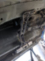

Very tight up top


Top-side it was time to check how all the previous work looked with the engine in place
Tensioner clearance looked very good
As did the alternator clearance. The alternator notch is so long because the goal was to make it so I could replace the alternator with the engine installed

The heater core bracket was also in a very good location
And the hose lined up properly

So all in all that was a huge win. I just stood back and took a few pictures of the V8 sitting in the Z3... very happy with how this is coming along at this point

And the hood still closes properly too!
Decided to throw the radiator core support back on and start mocking up radiators. I was really happy with the depth of the notch on the framerail on this side - my goal was to stop just short of the radiator and I accomplished that perfectly
This is a stock hose for a 6 cylinder model, this shows well how much further back the V8 sits than the I6

With some hoses in place. The upper hose I will be sourcing a different one but the I6 one stretched into position might... technically work... but I wouldn't run it like that

For anyone curious, the strut bar does not fit at the engine's current height

I then found a coolant line that was really nicely shaped to fit from the expansion tank to the engine

This is how I left it for the day. Starting to really come along

That night I ordered a bunch of parts and the next day I had a small project I've been meaning to knock out, I have some spare steel from the frame reinforcement so why not. When removing the radiator core support the mounting ears got mangled a little bit - they are spotwelded on, and sometimes require a little prying to get off, as I don't like to remove too much material by drilling too wide at the spotweld
So the goal here was to create something that acted sort of as a giant washer, to pull the ear flat as one piece when it was tightened down, as I was noticing previously it would pull in the ear around the bolt mount, but cause some waviness as it wasn't perfectly flat
Some more cardboard-aided design got me a template, which I marked out on the steel plate

A little trimming to shape, smoothing out the harsh edges. I'm pretty happy with how this came out considering the only tools I used to make it were an angle grinder with a cutting disc and then a flap disc (*do not try this at home!) plus a drill for the bolt holes

I could have gotten it a little tighter on the upper corner there but it was pretty hard getting it as precise as it was to begin with


I also test fit the Z3 PWM fan setup I made awhile ago. I made this for my personal 3.0 car by plastic welding the Z3 fan shroud tabs onto an E46 PWM puller fan. There was a TON of clearance. I may actually trim an E53 PWM fan assembly down to the correct size and see if I can make that fit instead, as the extra cooling ability of a higher wattage fan would certainly be welcome
I also hooked up the DME again and plugged everything back in to see if the DME was still communicating... very happy that it was! Doesn't mean a ton but it's nice to just ensure it's still communicating

It will be even better once I get the flywheel installed so I can test start it again!
Then I got the intake and radiator support bracket in so I could see if they would work... the E30 radiator support seems like it could have been made to fit, but once I fit the intake that was completely redundant

The intake is pretty huge and I had to remove the radiator to get it to fit
Intakes on each side... I think it's a very cool setup


Clearance issues in a few areas
And the hood didn't close so it started to seem like it wasn't going to happen

Buuut then I started to think about how I have like two or three spare Z3 radiator supports laying around so I started to think about what it would take to make it fit... I tried trimming a bit here, a bit there, ultimately I ended up just kind of sectioning out both sides and bending the middle down

The goal was to get it flush inside the core support so it would fit within the hood and it was starting to look good. After cutting the side sections out I knocked the inner bits out little by little and test fit it repeatedly until it was recessed the proper amount. Was also happy to get a chance to use my rivnut tool
It was looking good at this point but something was missing...

I measured up how much I had to drop the radiator by, compared to my S54 Z3 I had on hand and it seemed like the radiator would not be sitting lower than the oil cooler sits underneath the S54 radiator. So I went ahead and lowered the radiator support brackets the appropriate amount

And now it has a radiator again, it was very tight clearance to the intake... but these pieces should not move too much when driving


How it looks from the side
And the radiator hose fitment seemed a lot better at this height too, previously the upper hose was going to be leaning upwards a bit which did not seem ideal. It's hard to tell here but now the upper hose is sitting just about level now

And the (very dusty) hood closes now!
Definitely a bit excessive for just an intake but I really do like the look

Now that it's in place and the hood closes, it's time to finish modifying the radiator core support for the intake
In hindsight, it probably would have been a little easier and probably neater looking to just chop off that whole top section, without leaving the middle intact. I didn't know how far "down" it had to go though, so doing it this way allowed me to adjust it, test fit, adjust it, test fit until I got it where I wanted. But anyways - the side bits had to be chopped off as they were taller than the surrounding sheetmetal. So once cut out, it was time to fill the gaps
Stitched it in slowly - letting it cool in between welds. Not the prettiest welds but I'm definitely getting better at welding the BMW sheetmetal. That gap on the right side was fixed too, smoothed out once I was ready to weld that area

Then little side pieces were added and hammed around a round form (my jack handle) to get the contour correct. The lower part was tack welded, then I test fit the intake, made some adjustments, test fit again and when I was happy with where it sat I welded in the bottom of these side plates. Then I hammered them flush with the rad support along the top and started welding that together
It's hard to tell from this angle but the intake sits recessed into the rad support

This angle shows it a little better... when it's all done I'll clean up the welds - focusing especially on the ones that will be visible with the intake installed - and hopefully it will look like it was meant to be there!

I got the power steering pump in too. It had plenty of rear clearance but I was worried about the clearance in the front

With the sway bar all the way forward, it hits the pulley. I'm pretty sure in normal operation the swaybar will only move rearwards though - as the suspension is compressed, the "outside" arm of the sway bar moves up, which causes the span between the framerails to rotate rearwards. Right? Right...?

Then I looked over on my lift and what do I see? A Z3 M roadster! Went to look underneath it to compare clearance and look at this...
The stock Z3M A/C tensioner bracket has tighter clearance than the N62 power steering pump. And it would hit in the front if the swaybar moved forward. So this confirms what I was thinking earlier that in normal operation the swaybar will move rearward. I may need longer swaybar links though or may go to an M swaybar setup, I will see when things are a little closer but I am quite confident it can work...
Back to the dual intake install - this is turning out to be a lot more work than I anticipated after another day of work and you'll see why below. I am not convinced it is worth it to be honest at this point, but I'm already committed so I may as well finish it up
First thing I worked on was filling in this relief cut. I would do some spotwelds and then grind them down and repeat the process once the metal cooled

Then grinded them down
Repeated with some more spotwelds

And some more. My main focus here was to not grind the underlying metal too much but grinding the welds flush as you do them is supposed to help with achieving a cleaner end result so I wanted to give that a shot this time around. It seems to be working well
At one point once this process was done I decided I wanted to throw the intake on and plug the MAF in. I knew this MAF didn't plug into my engine harness, but what I didn't know was that the MAF that does plug in, doesn't simply bolt into this MAF housing - which is integrated into the intake itself
I had already started working on it at this point but you can tell the dual intake housing has an oval insert for the MAF. This is because the N62TU received a different style MAF with an oval shape. The older MAF, on the non-TU N62, had a circular shape. It did not fit in place at all

So as you can tell above, I decided to rectify this. My solution was to fill the opening with plastic JB weld and then I will drill out the filled in MAF port to the right dimensions in order to seat the old style MAF into this housing
I filled it in using a few layers in order to let it cure properly and eventually it looked like this
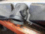
I then cut it down flush with an exacto knife
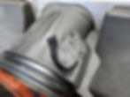
And applied a final layer to fill in some of those recesses
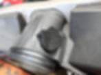
I have done this sort of thing a few times before and experimented with how to keep the inside contour correct. I got pretty decent results this time around

I did apply a little bit more to the inside though, to try to achieve as smooth a contour as possible and fill in a few areas that were recessed
For the record normally I would prefer to cut the flange area out of this MAF and graft it into the other piece but in this case, the contours did not line up at all

This area was close, but there wasn't anywhere on this plane to even try to mount it
And obviously the top just wasn't going to work

So I had to do it with this method. But it did work!
Once it was cured the next step was to sand the top surface down flush again, this time using a file and some elbow grease. There were some areas there were still slightly recessed, but it's a lot less than it looks like in person

And then taped it off and drilled the pilot hole, then the hole saw - monitoring the width of the hole relative to the width of the outside lip


This edge was not built up with epoxy to the top and there was a gap there that needed to be filled. So I taped off the inner contour, added some more epoxy then filed it again once cured

Test fit it for the first time... looking very good! Spent just a few minutes with my round file clearancing the hole to the right diameter and got it to fit perfectly, nice and snug

Then I got it screwed in place, one of the screws is different as I had to find a shorter one with the same thread pitch. I'll get a matching pair eventually
MAF is set in the correct depth and angled correctly into the airflow
And finally installed! This is the first time the engine has had the MAF plugged in
I then painted it... the paint said it was flat black but it dried to a dark gray kind of color. I might repaint it but it's not a big deal either way

Matching screws...

At this point I was still waiting on parts to be able to move forward with the critical stuff of the swap so I decided to wrap the intake in gold heat resistant tape
This had to be trimmed a bit too, for clearance around the coolant temp sensor

How it looks installed... I probably could have gotten away with just doing the front part over the radiator but more can't be a bad thing

I love Goooold!

And some more grinding and shaping of the radiator core support


The build continues in Part 17

